Just occasional scribblings of things I work on for a hobby. Hopefully, someone finds some of the content useful.
Tuesday, January 21, 2014
This blog has moved!!
Saturday, November 23, 2013
Testing for line segment intersection in 2D - a pedestrian approach
First, the problem: given two line segments L1 and L2, (a) do they intersect? (b) if so, where?
Before the algorithm we have to choose how we represent our lines. I prefer defining a line segment by two points:
$p_1=\left(x_1,y_1\right)$ $p_2=\left(x_2,y_2\right)$
This is a totally fine way of representing a line or a line segment. Another way of writing a line is:
$y = mx+b$
where the slope m and intercept b are related to our points as in the diagram below.
A disadvantage of writing the line as a function of y is that a vertical line (with equation x=const) can not be represented in this manner. If we're working with this form we have to consider vertical lines separately, which is a bit of a bummer, but amounts to a mere if statement or two.
Simple example: infinite lines
It helps to first consider the case of two lines. As drawn below, if the slopes of the two lines are equal, they always intersect at a unique point. If the slopes are equal, the lines do not intersect unless they are the same line, in which case (almost by definition), they intersect everywhere.// Simplest case:
double m1 = (L1.x2-L1.x1)/(L1.y2-L1.y1)
double m2 = (L2.x2-L2.x1)/(L2.y2-L2.y1)
double b1 = (y1-m1*x1)
double b2 = (y2-m2*x2)
// If the slopes are equal, they only intersect if the lines are equal
if(m1==m2)
{
if(b1==b2) return L1;
else return false;
}
else
// otherwise the lines intersect at a point
{
double xI = (b1-b2)/(m2-m1);
double yI = m1*xI+b1; // or m2*xI+b2 … same thing.
return return new Point(xI,yI);
}
Modifying for segments
// Modify for segments
if(lineCollision) // as before
{
if ((xI >= lx1 && xI <= rx1) && (xI >= lx2 && xI <= rx2))
{
collision == true;
}
}
Crossing the t's and dotting the ... lower case j's
if(L1.x1 == L1.x2)… with:
if(Math.abs(L1.x1 - L1.x2)<delta)
The code above will fail either of the line segments are vertical. This is easy to fix, but takes a few extra lines of code before the previous case:
// First check for vertical lines
if(L1.isVert()&&L2.isVert())
{
if(Math.abs(L1.x-L2.x)<delta) // they're the same line
{
if(L1.y2 > L1.y2 && L1.y1 < L2.y2) // they intersect
{
collision = true;
// xI,yI are on L1,L2
}
}
}
else if (L1.isVert())
{
xI = L1.x1;
yI = m2*xI + b2;
}
else if (L2.isVert())
{
xI = L2.x1;
yI = m1*xI + b2;
}
where,
public boolean isVert(Line L1)
{
return(L1.x1-L2.x2 < delta)
}
Finally, int the case of collinear segments, the intersection occurs not at a point, but over a smaller line segment itself. For my purposes I only care that the segments overlap at least at a point, but we can easily extend the code to give the segment of overlap:
public boolean isVert(Line L1)
{ // This assumes that x1<x2, y1<y2.
// If not, define x1s = Math.min(x1,x2);x2s = Math.max(x1,x2); etc…
// if colliding and collinear as before
double xL = Math.max(L1.x1,L2.x1);
double xR = Math.min(L1.x2,L2.x2);
double yL = m1*XL+b1;
double yR = m1*XR+b1;
return new LineSegment(xL,yL,xR,yR);
} // and similarly for horizontal and vertical lines
The Code in Action
Thursday, October 31, 2013
Arduino Round V: Light Seeking Robot
Stepper motor(768, in1Pin, in2Pin, in3Pin, in4Pin); // These pins are the outputs from the arduino. '768, refers to then number of steps per full motor rotation motor.setSpeed(speed); // After about a speed of 20, it barfs motor.step(N); // With a bipolar driver, a positive or negative N can be used for clockwise/counter clockwise rotation
The project I decided on to have a little fun with the motor was a "light-seeking robot". The robot would have a left and right eye (photoresistors) and would rotate via the stepper motor until both eyes measured equal brightness.
To accomplish this, we can subtract the right-eye's voltage from the left-eye's voltage to for an error signal. If there is more light to the right than to the left, a positive error signal results and the motor turns right. If the left side is brighter, the difference is negative and the motor turns left. At some point, the difference goes to zero at which point the motor doesn't turn at all. Furthermore, as the balance gets better, and the difference gets smaller, the robot slows down and smoothly approaches the Goldie-Locks amount of light on each eye. On the other hand, when the balance is way off, the error signal is huge and the motor corrects more strongly, a situation known as proportional feedback. If the motor had some inertia we'd have to add a little lag (integration) to the loop so that the robot didn't overshoot when it got to zero and oscillate back and forth but for a stepper motor, which is heavily damped, this is not a problem.
The eyes of the circuit are shown here: the photodiodes each are part of a voltage divider which go to separate arduino inputs. The eyes are attached to a decapitated lego figure (you gotta use what you got) whose rectangular feet fit nicely into the stepper motor.
The motor is driven by the following code:
#include "stepperh.h"
int in1Pin = 4;
int in2Pin = 5;
int in3Pin = 6;
int in4Pin = 7;
const int LEFT = A0; // Analog input pin
const int RIGHT = A1; // Analog input pin
int vL = 0;
int vR = 0;
int j = 1;
int m = 1; // polarity. If turning the wrong way, switch sign
int speed = 20;
Stepper motor(768, in1Pin, in2Pin, in3Pin, in4Pin);
void setup()
{
Serial.begin(9600);
pinMode(in1Pin, OUTPUT);
pinMode(in2Pin, OUTPUT);
pinMode(in3Pin, OUTPUT);
pinMode(in4Pin, OUTPUT);
pinMode(LEFT, INPUT);
pinMode(RIGHT, INPUT);
motor.setSpeed(speed);
}
void loop()
{
vL = analogRead(LEFT); // 0-5v <-> 0-1023
vR = analogRead(RIGHT); // 0-5v <-> 0-1023
Serial.print("Left = ");Serial.print(vL); // Log the measured values for debugging
Serial.print(", Right = ");Serial.print(vR);
Serial.print(", Difference = ");Serial.print(vR-vL);
Serial.print("\n");
motor.step(m*(vR-vL));
delay(250); // update at 4 Hz
}
The circuit layout is sketched here:
... and here's a video of the light seeking robot seeking light:
Thursday, October 10, 2013
Arduino Round IV: A Simple Character LCD
The LCD I used was a HD44780 compatible 4x20 character LCD that I got on the cheap from an overseas shop called seeed studia bazaar. It shipped from China so it took a couple weeks and shaved a few bucks - in the future I'd probably spend another $2 and get it overnight from somewhere a little more local.
The first chore is to hook up some solder pins to the LCD board which allows you to stick the LCD module into a solderless breadboard. With my $10, 10 year old soldering iron that I got from Walmart back in the day this was more painful than it needed to be.
Now that we can access the pins, the pin layout is as follows:
To do a basic test of operations, we can start by powering the module up and verifying that it works. Pins 1 and 2 power the unit, 15 and 16 power the back light, and pin 3 sets the LCD contrast. The datasheet for the LCD recommends a 5k potentiometer between pins 2 and 3 to set the contrast, but this could be replaced with a voltage dived from the voltage pin or a PWM output, directly from the Arduino. I found that a good value to sent to pin three was around 900mV. Here a picture of the"first light" of the project. The inset is what the screen looks like with 900mV contrast setting (my poor photography couldn't capture the bright backlight and the circuit simultaneously.)
Next, we need to hook up the data bus: for regular 4 bit operation, pins 11-14 receive information, which we can hook up to Arduino outputs 9-12. We also need to tell the LCD module three things:
- Whether the data being received are instructions or data to be displayed. This is selected via the register select (RS) pin 4. The Arduino Liquid crystal library which is to be used takes care of that, but for now, send an Arduino output port (4, say) to RS.
- Whether we are writing data to (5V) the chip or reading from it (GND). This is pin 5, R/W. Since we're only writing to the chip, we'll just clamp pin 5 to ground.
- Data enable (pin 6) which gates the unit for receiving data. Connect this to Arduino pin 5.
#include// Connections: // rs (LCD pin 4) to Arduino pin 4 // enable (LCD pin 6) to Arduino pin 5 // LCD pins d4-d7 to Arduino pins 9-12 LiquidCrystal lcd(4, 5, 9, 10, 11, 12); void setup() { lcd.begin(20,4); // Initialize a 20x4 HD44780-compatible LCD lcd.clear(); // clear the screen lcd.setCursor(0,0); // set cursor to column 0, row 0 (the first row) lcd.write("The Rules:"); // Write text, starting here lcd.setCursor(0,1); lcd.write("1. Don't harm humans"); lcd.setCursor(0,2); lcd.write("2. Obey human orders"); lcd.setCursor(0,3); lcd.write("3. Protect yourself"); } void loop() { }
The result, as well as the wired circuit being:
OK, now that we can write to the device, let's make it slightly more interesting by adding some real time data. We'll monitor the voltage across a photoresistor by placing it in voltage divider configuration and sending it to Arduino input pin A0. The luminosity is in arbitrary units since I have no idea what either the spectral content of the light in my living room is or what the spectral response of the photoresistor happens to be. We will then just output the brightness in arbitrary units with the understanding that the bigger the number, the brighter the environment. I also placed a capacitor in parallel with the second resistor to ground to smooth out the readings a bit. Not really necessary but it makes the look and feel a little nicer. As for the temperature, when pins 1 and 3 have 5V across them, pin 3 holds a voltage which is linearly related to temperature. The datasheet gives a graph which seems to state: $V_{out} = 10\frac{mV}{^\circ C}T+500mV$.
We can then invert this equation to find the temperature in Celcius is $T_C=50\left(2V_{out}-1\right)$ where $V_{out}$ is measured in Volts. The wiring for the sensors is sketched here:
In the Arduino code, we simply poll the input pins each loop and display the converted quantities. One final quirk - there is no degree sign that I could find in standard ascii. Luckily, the LCD allows you to program your own characters. This is a relief since it allows me to avoid using Fahrenheit. To build your own character, you just treat each row of 5 as a 5-bit binary number, with 1's where you want a pixel lit. There is a nice tool on the web which allows you draw your own character and it gives you the resultant binary number array. That's all we need. The code is:
#include// Connections: // rs (LCD pin 4) to Arduino pin 4 // enable (LCD pin 6) to Arduino pin 5 // LCD pins d4-d7 to Arduino pins 9-12 LiquidCrystal lcd(4, 5, 9, 10, 11, 12); // Input pins const int LIGHT = A0; const int TEMP = A1; // Varibales to store temperature value int tmp = 0; // To hold text strings char tVal[4]; char lVal[4]; // Create custom "degree" character pixelmap byte deg[8] = {B110,B1001,B1001,B110,B0,B0,B0}; void setup() { // Set up input pins pinMode(LIGHT,INPUT); pinMode(TEMP,INPUT); // initial custom character(s) lcd.createChar(1, deg); lcd.begin(20,4); // Initialize a 20x4 HD44780-compatible LCD lcd.clear(); // clear the screen } void loop() { // Static display text lcd.setCursor(0,0); lcd.print("Light Sensor:"); lcd.setCursor(0,2); lcd.print("Temperature (TM36)"); // Converst the voltage accross the thermistor to a temperature. tmp = ((675.0*analogRead(TEMP)/1280)-50.0); // Read the value of the photoresistor, in arbitrary units into a string. sprintf(lVal,"%d",5*analogRead(LIGHT)); // and print to the LCD lcd.setCursor(0,1); lcd.write(lVal); lcd.write("mV"); // I had to insert a delay, otherwise the display looked flickery. delay(200); lcd.clear(); // Prabably best to clear() directly after the delay sprintf(tVal,"%d",(int)tmp); lcd.setCursor(0,3); lcd.write(tVal); // lcd.setCursor(2,3); lcd.write(byte(1)); // lcd.setCursor(3,3); lcd.write("C"); }
Finally, here is the end result - and opto-temperature sensor:
Next, to toy with the motors and to try and built a python based oscilloscope.
Sunday, September 22, 2013
Arduino Round III: Trying to Listen to the Computer
Given that I don't know Python worth a dang, the most challenging part was the Python. First, I searched google for Python GUI, and found a plethora of packages. After a brief browse I went for the "native package" TkInter. Starting with a few lines of example code, I got the buttons, slider bars and everything on the screen. Writing to serial was as simple as writing to a console via serial.write().
The GUI, show above, was to have buttons to connect to the Arduino via the serial port, three sliding scrollbars for red green and blue LED intensity, and a 'disco mode' button which cycles through the colours. The program window is shown here:
There were a few nuisances. One of them was in naming. What I wanted was a sliding widget which was a scrollbar returning an interger withing a specific range. In Java, it's called a Scrollbar. In tKinter, a Scrollbar is a separate object, which is attached to other objects. What I really wanted was a "Scale". Next, in Java, there is a function called whenever the Scrollbar is updated, so that when the user slides from 12 to 25, you can automatically run code. As far as I could tell, this is not the case in TkInter. There are several quick workarounds: one is to have a button run a function which polls the Scales. A slightly better solution is binding which allows you to run code every time some pre-determined thing (releasing the right mouse-button for example) in a widget.
The code I used is here:
from Tkinter import *
import serial
import time
class Application(Frame):
# Store LED brightness, stored as integers, sent as bytes
rBrightness = -1
gBrightness = 0
bBrightness = 0
# Slight delay between sending serial data so as not to miss a char
# Possibly unnecessary.
delay = 0.01
# Strictly for keeping track of what label to put on buttons
on = False;
discoOn = False;
# GUI action Function definitions
# Open or close the serial port connection. For now hardwired to COM3
def toggle_connect(self):
if self.ser.isOpen():
self.ser.close()
print("Closed COM 3")
self.COM["text"] = "Open",
else:
self.ser = serial.Serial('COM3', 9600, timeout=0)
print("Opened COM 3")
self.COM["text"] = "Close",
# Shuts down the python interpreter. Last resort for port closing
def shut_down(self):
self.ser.close()
exit()
# Send a code to Arduino to switch LED off.
def send_on_off(self):
self.ser.write('0')
if self.on:
self.on = False
self.LED["text"] = "Turn On LED"
else:
self.on = True
self.LED["text"] = "Turn Off LED"
# Disco light show baby.
def disco_on_off(self):
self.ser.write('d')
if self.discoOn:
self.discoOn = False
self.disco["text"] = "Start Party"
else:
self.discoOn = True
self.disco["text"] = "Stop Party"
# Sends RGB values to the arduino encoded as a 'char'
# Method is bound to mouse clicks on the slider
def update_LED(self,event):
self.rBrightness = self.scaleRed.get()
self.gBrightness = self.scaleGreen.get()
self.bBrightness = self.scaleBlue.get()
print("(R,G,B) = (%i,%i,%i)") %(self.rBrightness,self.gBrightness,self.bBrightness)
self.ser.write('1')
time.sleep(self.delay)
self.ser.write(str(unichr(self.rBrightness)))
time.sleep(self.delay)
self.ser.write('2')
time.sleep(self.delay)
self.ser.write(str(unichr(self.gBrightness)))
time.sleep(self.delay)
self.ser.write('3')
time.sleep(self.delay)
self.ser.write(str(unichr(self.bBrightness)))
# GUI stuff
def createWidgets(self):
# First, create buttons
self.QUIT = Button(self)
self.QUIT["text"] = "QUIT"
self.QUIT["fg"] = "red"
self.QUIT["command"] = self.shut_down
self.COM = Button(self)
self.COM["text"] = "Open",
self.COM["command"] = self.toggle_connect
self.LED = Button(self)
self.LED["text"] = "Turn On LED"
self.LED["command"] = self.send_on_off
self.disco = Button(self)
self.disco["text"] = "Start Party"
self.disco["command"] = self.disco_on_off
# Sliders (if this were java, I'd say scroll bars. In python, scrollbar is another thing altogether)
self.scaleRed = Scale(self,from_=0, to=255)
self.scaleRed["bg"] = "red"
self.scaleGreen = Scale(self,from_=0, to=255)
self.scaleGreen["bg"] = "green"
self.scaleBlue = Scale(self,from_=0, to=255)
self.scaleBlue["bg"] = "blue"
# Add widgets to the screen
self.QUIT.pack({"side": "left"})
self.COM.pack({"side": "left"})
self.LED.pack({"side": "left"})
self.scaleRed.pack({"side": "left"})
self.scaleGreen.pack({"side": "left"})
self.scaleBlue.pack({"side": "left"})
self.disco.pack({"side": "left"})
# Bind scrollbars to mouseclicks
self.scaleGreen.bind('',self.update_LED)
self.scaleBlue.bind('',self.update_LED)
self.scaleRed.bind('',self.update_LED)
# initialize GUI
def __init__(self, master=None):
Frame.__init__(self, master)
self.pack()
self.createWidgets()
self.ser = serial.Serial('COM3', 9600, timeout=0)
self.ser.close()
root = Tk()
app = Application(master=root)
app.mainloop()
root.destroy()
The Arduino code was next. The idea was to have have the Arduino constantly looking for a new char sent through the COM port. If it receives a particular character, it will change state accordingly. For example, a '0' will toggle the LED output on or off. A 'd' will start disco party mode. A '1', '2', or '3' will put the chip in a listening state for red, green or blue respectively. In this state, the next char received is assigned to the corresponding LED's brightness. The code shown here:
// Accept commands from serialComm.py Python script
// Controls the RGB values of a 3-color LED.
// Optional 'disco mode' which cycles through the colours
// Author: Andrew MacRae (macrae@berkeley.edu)
// PWM output ports
const int RLED = 9;
const int GLED = 10;
const int BLED = 11;
// Device states
const int LISTEN = 0; // Accepting data.
const int READ_RED = 1; // next char read assigned to RED.
const int READ_GREEN = 2;// Same, but for green.
const int READ_BLUE = 3; // ditto, for blue.
boolean on = false; // Outputing to the LED?
boolean disco = false; // Disco mode
// Stores the RGB values recieved from the GUI
int rBright = 28;
int gBright = 128;
int bBright = 68;
// For disco mode. These will be automatically adjusted
int iR = 0;
int iG = 0;
int iB = 0;
byte byteRead = 'x'; // current byte read from serial
int state = LISTEN; // Initially, wait for instructions
// Setup ports for input and start the serial connection
void setup()
{
pinMode(RLED, OUTPUT);
pinMode(GLED, OUTPUT);
pinMode(BLED, OUTPUT);
Serial.begin(9600);
}
// main loop
void loop()
{
if (Serial.available())
{
// is a byte has been sent, store it
byteRead = Serial.read();
// If previously recieved instruction to read in colour,
// set the value to that of the byte and reset state to LISTEN
if(state == READ_RED)
{
rBright = byteRead;
state = LISTEN;
}
else if(state == READ_GREEN)
{
gBright = byteRead;
state = LISTEN;
}
else if(state == READ_BLUE)
{
bBright = byteRead;
state = LISTEN;
}
// Otherwaise, check if state change is needed:
// 'd' means toggle disco mode
else
{
if(byteRead == 'd')
{
disco = !disco;
}
// '0' means toggle output on/off
if(byteRead == '0')
{
on = !on;
byteRead= 'x';
}
// '1'/'2'/'3' means prepare to read in red/green/blue
if(byteRead == '1')
{
state = READ_RED;
}
if(byteRead == '2') // Toggle On/Off
{
state = READ_GREEN;
}
if(byteRead == '3') // Toggle On/Off
{
state = READ_BLUE;
}
}
}
// if the LED is on
if(on)
{
// loop disco mode variables
iR+=3;
iG+=5;
iB+=7;
if(iR>255) iR=0;
if(iG>255) iG=0;
if(iB>255) iB=0;
// and use these variables if in disco mode
if(disco)
{
analogWrite(RLED,iR);
analogWrite(GLED,iG);
analogWrite(BLED,iB);
delay(30);
}
// otherwaise use the variables set by the user
else
{
analogWrite(RLED,rBright);
analogWrite(GLED,gBright);
analogWrite(BLED,bBright);
}
}
// if off, set all outputs low
else
{
digitalWrite(RLED,LOW);
digitalWrite(GLED,LOW);
digitalWrite(BLED,LOW);
}
}
The circuit is simplicity itself. Three separate PWM outputs are sent to the led which is grounded through a 100 Ohm resistor. The green and blue chanels get an extra 220 Ohms to set the relative brightness of each LED about equal. A sketch is included below:
Finally, here's a very crappily shot video of the circuit in action! To reduce the brightness and display the colour more uniformly, I used a high-tech solution known as a Perforated Fibrous Diffusive Membrane. Paper towel to the layperson.
http://www.youtube.com/watch?v=MZN09ancg_U
Saturday, September 14, 2013
Arduino Round Two: Trying to Talk to the Computer
const int PHOTO = A0; // Analog input pin
int voltage = 0;
void setup()
{
Serial.begin(9600);
}
void loop()
{
voltage = analogRead(PHOTO); // 0-5v <-> 0-1023
Serial.println(voltage); // Plain ASCII
delay(250); // update at 4 Hz
}
The circuit is even more simpleminded: the photoresistor's resistance varies from about 10k when dark, to just under 1k when I have my phone's flashlight on it. Placing the analog in port between this and a 10K resistor makes a nice voltage divider which goes from about 50% to 95% of whatever you feed it, which in this case, is 5V:
Actually, if you just want to see data sent from an Arduino chip over the serial port, the built in serial monitor works right away.
However, if you want a nice plot, you have to deal with that yourself. I know Java pretty well, so that was my first instinct. I keep hearing about Python though and how amazing it is. I decided to give it a shot and downloaded Python 3.x for windows. Then I read up on connecting to a COM port and apparently, the best bet is to install a module known as pySerial. I went an got ahold of that, and ... it didn't work. I was having trouble with loading the python module and after a brief search, concluded that I'd better downgrade to Python 2.x. I got that and after dome fiddling, could read from the COM port, albeit with some lag. To fix the lag, it turns out that you have to poll the arduino faster than the arduino is writing out, otherwise you get a backbuffer. I believe you can also solve this with a flush of the serial port.
OK, but I still haven't plotted anything. To get going on that , I read about MatPlotLib for Python for which I needed numPy. I went to download that, and as it turns out, I should have installed a Scientific Python distribution instead of plain old Python. Again, I uninstalled Python and installed EndThought Canopy - a gargantuan download/install which in the end, had major trouble with pySerial. At this point, what was another uninstall, so I dumped it and went for Continuum Anaconda. Using this, I could get a plot up and running - well up, but not running.
Long story short, if you want to plot things in real time with MatPlotLib, you need to give the graphics library to sort itself out, or the window will hang. This can be done via a simple 'sleep' command. The program that eventually worked is shown below:
# Poll a COM port for Serial data and plot real time
# Thanks to http://www.lebsanft.org/?p=48 for the code idea
import sys
sys.path.append('C:\\Python27\\lib\\site-packages')
import serial
import time
import numpy as nm
from matplotlib import pyplot as plt
ser = serial.Serial('COM3', 9600, timeout=0)
yData = [0]*50
ax1=plt.axes()
line, = plt.plot(yData)
plt.ylim([800,1100])
while 1:
# First, read from the device
try:
currVal = ser.readline()
print(currVal)
time.sleep(.1);
except ser.SerialTimeoutException:
print('Error acquiring data')
# Check if the data was a valid number ...
# may be blank in asynchronous mode
try:
cV=float(currVal)
runnit = True
except:
runnit = False
# If the value was a legit number, plot it.
if runnit:
ymin = float(min(yData))-10 # Set the y-scaling
ymax = float(max(yData))+10
plt.ylim([ymin,ymax])
yData.append(currVal) # tag on newest point
del yData[0] # and bump oldest point
line.set_xdata(np.arange(len(yData)))
line.set_ydata(yData) # update the data
plt.show() # update the plot
plt.pause(.01)
# Doesnt exit nicely here ... need to fix
Finally, real time monitoring of, well ... of my shadow here. But I see it as a next step to bigger and better projects:)
Thursday, September 12, 2013
An attempt at Arduino
I kept hearing about this thing called Arduino. which seems to be a good place to start. Utilizing an upcoming birthday, I hinted heavily to my wife that the perfect gift for a geek like me was a "get your feet in the water" Arduino kit. My pressing hints payed off and I've just started fooling around with my new Arduino Uno.
Upon first glance, Arduino seems pretty awesome. It is a composite microcontroller/programming board which gives you easy access to a number of digital/analog i/o pins. Despite the convenience of this, I was initially put off by this. During my brief stint with AVR programming, I could remove my little ATMEGA chip, and stick it in a small box containing a 9V battery and a tiny breadboard and have my device. If I wanted to make a couple, I just needed the ICs, and not several copies of the programmer, which scales up the size and cost of a duplicate project.
I have this dream of placing a bunch of ICs on a breadboard for individual projects, rather than chunking together a bunch of Arduinos. However, discussions such as this one have convinced me that under the hood, an arduino is simply a special a AVR programmer, and if I wanted to, I could use the arduino board to program AVR chips just the same. So for now, I'm sold, and am excited to get started.
Apparently, the equivalent of "hello world" in the microcontroller world is to blink an LED, so that was my first step. I found a quick tutorial on this and, as is my habit, tried to modify it a little from the get go. As a first selling point to Arduino, it was about three minutes from opening the box to getting a simple program running.
The first step was to download the Arduino software which allows you to either debug, or upload your program with the click of a button. The next step was to wire up a simple circuit board to do my bidding. The idea for this first program is simple: When the user clicks a button, slowly ramp up the voltage to an LED from whatever it was to a maximum value. When the button is pressed again, it slowly ramps down to 0.
The code for this is simple: A button press toggles the state of the device between on and off. When its on(off) the device increments(decrements) the brightness (which is just a PWM voltage) and delays for 10 ms. That's pretty much it. There is a bit of weirdness of the switch bouncing which can be remedied by introducing a slight delay after switching states:
const int aLED = 9; // Analog LED
const int BUTTON = 7; // Push Button
boolean buttVal = 0; // True if button pressed
boolean buttValOld = 0; // Value from last cycle
boolean on = false; // Stores the state' of the device
int brightness = 0; // Stores the brightness value from 0 to 255
void setup()
{
pinMode(aLED, OUTPUT); // Set pin9 for output
pinMode(BUTTON,INPUT); // Set pin 7 for input
}
void loop()
{
// Handle a button press. If the state has changed, delay for 5ms
// to avoid bouncing
buttVal = digitalRead(BUTTON);
if(buttVal&&!buttValOld)
{
on = !on;
delay(5);
}
buttValOld = buttVal;
if(on) // If state is on, ramp up voltage each cycle, then delay
{
if(brightness<255)
{
brightness++;
delay(5);
}
}
else // If state is off, ramp down voltage each cycle, then delay
{
if(brightness>0)
{
brightness--;
delay(5);
}
}
// Finally, set the LED voltage to the current value of 'brightness'
analogWrite(aLED,brightness);
}
The circuit itself is also is exceedingly simple: depressing the switch routes 5V to the input pin 7, which causes digitalRead(BUTTON) to return a "HIGH" state. The LED voltage is run through a 270 Ohm resistor to ground to limit the current drawn from output pin 9.
The result .... is pretty much what you'd expect:
I had a lot of fun with this one and am looking forward to the next mini project-ling.
Sunday, June 26, 2011
Tick Counter for Slow Computers
while(Playing)
{
updateGame();
System.pause(delayTime);
}
which is fine as long as the game code executes in a time much less than the refresh period (i.e. 1/(refresh rate)). However, when the game loop takes a longer time so that the delay you need to give is quite small, then the computer optimized for a slower computer (as I have at home) will run way too fast on a less ancient computer (as I have at work.)
This can be partially overcome (assuming that you computer can at least run the program with zero delay) by implementing a feedback loop which adjusts the delay time to keep a fixed number of cycles per second.
This is actually quite easy to do: say we want x cycles/s and we get y cycles/s -
int t = getCurrentTime();
int tickCounter = 0;
while(Playing)
{
tickCounter++;
time = getCurrentTime()-t;
if(time > 1000ms)
{
delay = updateDelay(tickCounter);
t = getCurrentTime(); // reset time
tickCounter=0;
}
updateGame();
System.pause(delay)
}
public int updateDelay(int y)
{
return delay*y/x;
}
... and that's it.A simple implementation of this can be found here: basically, it is an Applet which runs a stopwatch (it has to do something) and adjusts the delay per loop so that the program executes a specified number of iterations per second. The functionality of the stopwatch is unaffected by the background feedback loop as desired.
... and the source code is here.
Saturday, November 13, 2010
Side Scrolling Fun V: Music, Levels, Bosses, and Media Managers
The next fish to fry was sound - both sound effects and soundtracks. I started by making a sound manager (sMan) similar to the image manager. Next I had some struggle with sound formats. Java doesn't care much for wav files. I basically had to tinker with the bit-rate, depth, etc. to get it to play, and I still don't know why some play and some don't. All I can say is that the java native sound engine is good, but finicky. As for sound track, I went for straight up midi which was a lot easier to work with. Currently, all the songs are ripped off from an awesome repository of nes roms that I came accross and I am starting to try to "compose the original score" :)
The next task was to create game states that allowed specific tasks to occur (ex. loading, player just died, player is playing, etc.) This allowed for an intro screen when the game was loading and cut-scenes between levels. This also allowed for animations and sound clips to run when the player dies or beats a level. The paint and run methods are then if-else statements based on the current state. The states are:
- Intro
- LoadIntro
- LoadLevel
- Playing
- JustDied
- Boss
- JustPassed
Friday, October 1, 2010
Side Scrolling Fun IV: Enemies, Mortality and Backgrounds
double screenX = 0;
if(xCX)
{
screenX = CX;
}
else if(x>levelMaxX-CX)
{
screenX = levelMaxX-CX;
}
else screenX = x;

To make it so the player could die, I just check for special cases in the collision detection. For example if the player collides with a spike, he dies. If the player collides with an enemy from below or the side, he dies, but if he collides from above, the enemy dies. Here the player dying means that his 'lives' get reduced by one, and he's warped to the beginning of the level. Now, nothing happens if he runs out of lives he just has a negative amount of lives. The philosophical implications are mind boggling!
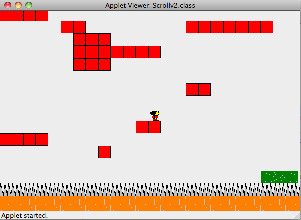
Here is a screen-shot of the program in action. Click on the pic to try the game. One problem is that the loading time is brutal. At first I thought that it was the server but after writing a simple test program which loads a single image and text file from the server I noticed that this was not the case, as the test program ran instantly. Upon closer inspection I think it's just that I was being stupid. When the level is loaded it loads each tile as an image from a URL which is ridiculous. For next iteration of the program I'll just load each item once (via a LoadManager?) and store these images as global type files.
Saturday, September 11, 2010
Side Scrolling Fun III: Sprites & Tiles
- s: Standing and facing right
- S: Standing and facing left
- j: Jumping and facing right
- J: Jumping and facing left
- r: Running and facing right
- R: Running and facing left

Thursday, September 9, 2010
Side Scrolling Fun II: The Level Editor
Monday, August 30, 2010
Side Scrolling Fun
- calculates his next position
- checks for collisions at this position against a list of squobs
- handles collisions and applies drag

Saturday, October 10, 2009
Why Do Planes Get Lift?

Assume that the air flow is non-turbulent, (basically, this means that two air molecules next to each other at the front of the wing will meet at the back of the wing if one takes the upper path and the other takes the lower path. If this is not the case, air would be accumulating above or below the wing and at the back, you'd get vortex effects - i.e. turbulence.)
Note that the wing is slightly longer on top then on the bottom. The bottom is of length L, and the top is of length L + dL, where dL is small compared to L. To emphasize this, lets say:
d = dL/L ... (1)
Since the flow above the wing has to travel a farther distance than the that of the bottom path in the same amount of time (non-turbulent flow), the air on the top is going faster than the air on the bottom.
Since velocity = distance/time, we have:
velocity on bottom = vb = L/t ... (2)
and on top = vt = (L+d)/t = vb + d/t = vb + L/t*d/L = vb(1+d) ... (3)
where in that last step, I used (1).
Now it's time for Bernoulli's equation: it says that, assuming non-turbulent flow, the pressure P, velocity v, and height h, of a fluid with density ρ at points htop and hbot are related by:
Ptop + 1/2 vtop^2 + ρ g htop = Pbot + 1/2 ρ vbot^2 + ρ g hbot ... (4)
The first thing to note is that htop~ hbot, so the lift due to these terms (buoyancy) can be neglected:
ρ g htop ~= ρ g hbot ... (5)
To be convinced of this, the density of air is around 1 kg/m^3 and a wing is about 0.1m thick. Since g is about 10 m/s^2, the differential pressure is on the order of 1 Pascal. For a 10 m^2 wing, this could lift about 1kg, which is much less than the wing itself would weigh.
Next note that the quantity that we're interested in is Force due to the differential pressure. Since Force = Pressure x Area, this is, for wings of area A:
Flift = (Pbot - Ptop)*A ... (6)
Combining (4) through (6), we get:
Flift = 1/2 ρ (vtop^2 - vbot^2)*A ... (7)
We can now use (2) and (3) to get:
(vtop^2 - vbot^2) = vbot^2 (2d -d^2) ~ 2dvbot^2 ... (8)
In the last step, we used the fact that d << 1bot = v, the velocity of the plane, we get:
Flift =ρ A d v^2 ... (9)
... the force of lift due to the wings.
Let's say that the top path of the wing is 5% longer (d=0.05) and that each wing is 10 m^2. Using ρair = 1 kg/m^3, we get:
Flift = v^2, with Flift in Newtons and v in meters/second. In order for the plane to fly upwards, the force of lift must be greater than the force of gravity Fg = m g.
A typical jet can fly at around 200 to 250 m/s, so the force of lift is then about: 62,500 N (now we see why the ρ g h terms could be ignored.) This can lift a mass of 6,250 kg, but a jet weighs in at a few 100,000 kg, so why does it fly?
First off, this is an oversimplified picture: this would work well for a glider or bird (a bird with 10cm x 40cm = .04 m^2 wings and d = 10% would have to go about 30 m/s to glide if it weighed a pound - any slower and it'd have to flap its wings.) A jet on the other hand, has propulsion which pulls it upward, in addition it gets an upward lift from the normal force of the wind. This is the same force that you feel when you stick your hand out of the window while driving down the highway. For a large jet such as a Boeing 747 this actually contributes to most of the lift force.
The point of this was to do a back of the envelope calculation of the "popular" idea of lift, and show that this simplified picture alone doesn't really explain why a jumbo jet flies way up in the sky. For a more details, the complexity of the problem goes up exponentially and you soon have to resort to numerical simulations. However, a really nice (slightly less simplified) discussion is found here!
Sunday, October 4, 2009
The Jog Mapper
Here's a screenshot of the program in action. The calibration is done at the beginning where you type in the scale and then drag across the scale-bar to define a conversion fact of meters/pixel. Then you click out your path in line-segments and the program keeps track of the total distance.

Right now, the program is very bare-bones. First off, you have to acquire the map image first, put it into bmp format, and make sure the scale is visible. What would be nice would be to dynamically load the map from mapquest. Second, the user interface is usable, but not friendly. However it does what it does well enough. Thirdly, it would be nice to be have segments that aren't lines, but as long as you don't mind a lot of clicking, it's not a problem.
The guts of the program are as follows: The program starts out in calibration mode. You type in the physical reading from the map's scale, and then click the mouse at the start and end of the scale to get the conversion factor of physical length per pixel. then the program is in the main mode. A display on the top left corner gives you the mileage (kilometerage actually.) When you click at your starting point the program is in draw mode, and a line follows the mouse cursor. Click again and the line segment formed is added to the Path() class. Each click thereafter adds a line segment and the distance continuously updates.
As of now it's a quick and dirty program. If I were to make some changes, it would be (in this order:)
- Make the program, resettable.
- Design the UI properly, including a file dialog box for the map.
- Make the window scrollable to allow for bigger maps.
- Get the maps real-time off the information super-highway. (I have no idea how to do this)
Monday, July 20, 2009
Capture the Flag II
The field itself consists of four regions:
1. The flag zone: The defending team can't go into it's own flag zone, and is a safe haven for an attacking player.
2. The defending zone: The defender and rescuers hang out here. When the enemy attacker is not in this zone, they just track his y-position, when he is, they go after him.
3. The attacking zone: Here, the attacker forms a vector which is the sum of vectors towards the flag, with vectors away from the defender and attacker, with given weights attached to each.
4. The safe zone: In the safe zone, the defender can not capture the attacker, so the attacker no longer tries to avoid anyone and goes straight for the flag. Once he has it, he makes a dash for it to his own zone.
As of now, the rescuer does absolutely nothing - he has the same instructions as the defender, except he isn't allowed to capture. Instead, when an attacker is captured, he has to do a strange sort of dance: first he has to go to the corner of his own zone, then he has to touch his own flag-holder, and then he starts again.The system often gets into a "deadlock scenario" in which both players eternally get captured, do their dance, and get captured at the exact same place. This problem could be avoided by imposing a time limit on each round and resetting after it expires (the positions of the players are randomized at the start of each round.)
Here's a video of the program in action:
Before doing the really hard part - the genetic algorithm part, one more programming run is needed, to iron out the kinks. This means:
- Make the program more modular (i.e. variable number of players for each team)
- Make a jail (to give the rescuers something to do)
- Clean up the player logic (there's a lot of ad hoc stuff in there right now to make it work)
- Add timers etc. and pretty it up a little.
Sunday, July 19, 2009
Twinkling Streetlights
The reason for the "twinkling of the stars" is what is called "atmospheric seeing": the atmosphere has layers of turbulent air of varying density and temperature, which leads to a time-varying index of refraction (The speed of light in a vacuum (outer space, say), divided by the speed of light in the material (air here.)) To see why this would make a star twinkle, recall that a lens is just a material of certain index of refraction, shaped in a certain way so as to focus (or diverge) light. The pockets of air blowing around the atmosphere, means that light from a star would rapidly become focused and unfocused as the air above blows around. This is kind of like the pattern you see on the sand, underneath shallow water: the light jumps around like crazy from being randomly bent at the surface. For water the effect is way more pronounced, since the index of refraction of water is about 1.33, whereas for air it's 1.0003 - just barely different than for a vacuum for which, by definition, it's 1. You can check how bad the current "seeing" is here.
So that's why stars twinkle, but then what about planets? The same "seeing effects" would be present for both planets and stars, but we only notice it for planets (actually, if you look through a telescope at Saturn or the Moon, you really start to notice the effects of seeing on a good night vs. a bad night.) The reason is that to us, stars come from a point in the sky - we can't resolve with our eyes what shape they are or what they look like. All our eyes know is that light is coming from one specific direction. When we see an object, say Winnie Cooper, her left ear is focused to one point on our retina, and her right ear is focused to another. That is, we can resolve the shape of the image. For stars, this is not the case: they're so far away that the left part of the star is totally smeared over with the right part of the star. Because light is wave, it can't be focused to an infinitely small point, the focus is limited (by diffraction) to a certain size, and for stars, this size is much bigger, that the size that they would be focused to on our retina. For planets however, we can make out the shape of them and although each point of the planet is experiencing this seeing effect, all of the combined effects average out into a steady (slightly blurred, if you look through a telescope) image. To verify this, we can to a rough calculation.
The minimum resolvable angular distance between two objects which are sent though a lens with diameter D is: sin(θ) = λ/D times some constant which is close to 1 and depends on the type of wave and the exact shape of the lens. For a plane wave through a perfectly circular lens, it is 1.22. For us, D is the diameter of our pupil, say 5 mm, at night. The wavelength of visible light is on the order of 600nm, so λ/D is about 10^(-4) which means that the minimum angle is about θ = 0.0001 (since sin(θ) is pretty much equal to θ when θ is so small.) Now by definition, sin(θ) = Dia/dist, where Dia is the diameter of the object and dist is the distance to it. We now have a test to see if an object is resolvable or not: if Dia/dist is bigger than 0.0001, it should be, if Dia/dist is much less that 0.0001, it's not (keeping in mind the roughness of the calculation.)
Several cases:
Mars: Dia = 6800 km, dist = 55000000 km, Dia/Dist = 0.00012
i.e It should just be resolvable.
Jupiter: Dia = 140000 km, dist = 700000000 km, Dia/Dist = 0.0002
i.e. Again, in the window of resolvability
α-Centauri (nearest star): Dia: 10^6 km, dist = 2*10^13 km, Dia/Dist = .0000005
=> much less that that of the planets.
Now, bringing this back to the original discussion, say that a street lamp has a diameter of about 10 cm. The distance at which it takes up about the same angle as a planet is: dist = Dia/θ = 1 km. Much farther than this, and the lights become point sources, like the stars. From where I live, the lights at the train-station 1 km from my place don't twinkle, but the lights on the ski-hill, 5 km away do. However, the giant billboards by the hill do not - they have a bigger Dia. and therefor are resolvable. These calculations were pretty rough, but they sketch out the main point - that the "twinkling" of stars and distant lights, stems from them being "point-sources" of light to our eyes.