Sunday, September 22, 2013

Arduino Round III: Trying to Listen to the Computer

Having read data from the Arduino to a computer, the next step was to figure out how to send data from a computer to an Arduino. Again, the Arduino framework made this a much easier task than I thought. The mini project that I chose to implement this was a simple GUI which controls the RGB values of a three colour LED. Really, this is identical to independently controlling three LEDs and would work the same way.

Given that I don't know Python worth a dang, the most challenging part was the Python. First, I searched google for Python GUI, and found a plethora of packages. After a brief browse I went for the "native package" TkInter. Starting with a few lines of example code, I got the buttons, slider bars and everything on the screen. Writing to serial was as simple as writing to a console via serial.write().

The GUI, show above, was to have buttons to connect to the Arduino via the serial port, three sliding scrollbars for red green and blue LED intensity, and a 'disco mode' button which cycles through the colours. The program window is shown here:


There were a few nuisances. One of them was in naming. What I wanted was a sliding widget which was a scrollbar returning an interger withing a specific range. In Java, it's called a Scrollbar. In tKinter, a Scrollbar is a separate object, which is attached to other objects. What I really wanted was a "Scale". Next, in Java, there is a function called whenever the Scrollbar is updated, so that when the user slides from 12 to 25, you can automatically run code. As far as I could tell, this is not the case in TkInter. There are several quick workarounds: one is to have a button run a function which polls the Scales. A slightly better solution is binding which allows you to run code every time some pre-determined thing (releasing the right mouse-button for example) in a widget.

The code I used is here:

from Tkinter import *
import serial
import time

class Application(Frame):
# Store LED brightness, stored as integers, sent as bytes
    rBrightness = -1
    gBrightness = 0
    bBrightness = 0
# Slight delay between sending serial data so as not to miss a char
# Possibly unnecessary.    
    delay  = 0.01
# Strictly for keeping track of what label to put on buttons
    on = False;
    discoOn = False;
# GUI action Function definitions        

# Open or close the serial port connection. For now hardwired to COM3
    def toggle_connect(self):
        if self.ser.isOpen():
            self.ser.close()
            print("Closed COM 3")
            self.COM["text"] = "Open",
        else:
            self.ser = serial.Serial('COM3', 9600, timeout=0)
            print("Opened COM 3")
            self.COM["text"] = "Close",
# Shuts down the python interpreter. Last resort for port closing
    def shut_down(self):
        self.ser.close()
        exit()
# Send a code to Arduino to switch LED off.        
    def send_on_off(self):        
        self.ser.write('0')
        if self.on:
            self.on = False
            self.LED["text"] = "Turn On LED"
        else:
            self.on = True
            self.LED["text"] = "Turn Off LED"
# Disco light show baby.            
    def disco_on_off(self):
        self.ser.write('d')
        if self.discoOn:
            self.discoOn = False
            self.disco["text"] = "Start Party"
        else:
            self.discoOn = True
            self.disco["text"] = "Stop Party"        
# Sends RGB values to the arduino encoded as a 'char' 
# Method is bound to mouse clicks on the slider        
    def update_LED(self,event):
        self.rBrightness = self.scaleRed.get()
        self.gBrightness = self.scaleGreen.get()
        self.bBrightness = self.scaleBlue.get()
        print("(R,G,B) = (%i,%i,%i)") %(self.rBrightness,self.gBrightness,self.bBrightness)
        self.ser.write('1')
        time.sleep(self.delay)
        self.ser.write(str(unichr(self.rBrightness)))
        time.sleep(self.delay)
        self.ser.write('2')
        time.sleep(self.delay)
        self.ser.write(str(unichr(self.gBrightness)))
        time.sleep(self.delay)
        self.ser.write('3')        
        time.sleep(self.delay)
        self.ser.write(str(unichr(self.bBrightness)))
# GUI stuff        
    def createWidgets(self):
# First, create buttons        
        self.QUIT = Button(self)
        self.QUIT["text"] = "QUIT"
        self.QUIT["fg"]   = "red"
        self.QUIT["command"] =  self.shut_down

        self.COM = Button(self)
        self.COM["text"] = "Open",
        self.COM["command"] = self.toggle_connect

        self.LED = Button(self)
        self.LED["text"] = "Turn On LED"
        self.LED["command"] = self.send_on_off
        
        self.disco = Button(self)
        self.disco["text"] = "Start Party"
        self.disco["command"] = self.disco_on_off        
# Sliders (if this were java, I'd say scroll bars. In python, scrollbar is another thing altogether)        
        self.scaleRed = Scale(self,from_=0, to=255)
        self.scaleRed["bg"] = "red"        
        
        self.scaleGreen = Scale(self,from_=0, to=255)
        self.scaleGreen["bg"] = "green"        
        
        self.scaleBlue = Scale(self,from_=0, to=255)
        self.scaleBlue["bg"] = "blue"
# Add widgets to the screen                        
        self.QUIT.pack({"side": "left"})
        self.COM.pack({"side": "left"})        
        self.LED.pack({"side": "left"})
        self.scaleRed.pack({"side": "left"})
        self.scaleGreen.pack({"side": "left"})
        self.scaleBlue.pack({"side": "left"})
        self.disco.pack({"side": "left"})    
# Bind scrollbars to mouseclicks        
        self.scaleGreen.bind('',self.update_LED)
        self.scaleBlue.bind('',self.update_LED)
        self.scaleRed.bind('',self.update_LED)
# initialize GUI
    def __init__(self, master=None):
        Frame.__init__(self, master)
        self.pack()
        self.createWidgets()
        self.ser = serial.Serial('COM3', 9600, timeout=0)
        self.ser.close()

root = Tk()
app = Application(master=root)
app.mainloop()
root.destroy()

The Arduino code was next. The idea was to have have the Arduino constantly looking for a new char sent through the COM port. If it receives a particular character, it will change state accordingly. For example, a '0' will toggle the LED output on or off. A 'd' will start disco party mode. A '1', '2', or '3' will put the chip in a listening state for red, green or blue respectively. In this state, the next char received is assigned to the corresponding LED's brightness. The code shown here:


// Accept commands from serialComm.py Python script
// Controls the RGB values of a 3-color LED.
// Optional 'disco mode' which cycles through the colours
// Author: Andrew MacRae (macrae@berkeley.edu)

// PWM output ports
const int RLED = 9;
const int GLED = 10;
const int BLED = 11;
// Device states
const int LISTEN = 0;    // Accepting data.
const int READ_RED = 1;  // next char read assigned to RED.
const int READ_GREEN = 2;// Same, but for green.
const int READ_BLUE = 3; // ditto, for blue.

boolean on = false;     // Outputing to the LED?
boolean disco = false;  // Disco mode
// Stores the RGB values recieved from the GUI
int rBright = 28;        
int gBright = 128;
int bBright = 68;
// For disco mode. These will be automatically adjusted
int iR = 0;
int iG = 0;
int iB = 0;

byte byteRead = 'x'; // current byte read from serial
int state = LISTEN;  // Initially, wait for instructions

// Setup ports for input and start the serial connection
void setup()
{
  pinMode(RLED, OUTPUT);
  pinMode(GLED, OUTPUT);
  pinMode(BLED, OUTPUT);
  Serial.begin(9600);
}
// main loop
void loop()
{
  if (Serial.available())
  {
// is a byte has been sent, store it    
    byteRead = Serial.read();
// If previously recieved instruction to read in colour,
// set the value to that of the byte and reset state to LISTEN
    if(state == READ_RED)
    {
      rBright = byteRead;
      state = LISTEN;
    }
    else if(state == READ_GREEN)
    {
      gBright = byteRead;
      state = LISTEN;
    }
    else if(state == READ_BLUE)
    {
      bBright = byteRead;
      state = LISTEN;
    }
// Otherwaise, check if state change is needed:

// 'd' means toggle disco mode
    else
    {
      if(byteRead == 'd')
      {
        disco = !disco;
      }
// '0' means toggle output on/off
      if(byteRead == '0')
      {
        on = !on;
        byteRead= 'x';
      }
// '1'/'2'/'3' means prepare to read in red/green/blue
      if(byteRead == '1')
      {
        state = READ_RED;
      }
      if(byteRead == '2') // Toggle On/Off
      {
        state = READ_GREEN;
      }
      if(byteRead == '3') // Toggle On/Off
      {
        state = READ_BLUE;
      }      
    }        
  }
// if the LED is on  
  if(on)
  {
// loop disco mode variables    
    iR+=3;
    iG+=5;
    iB+=7;    
    if(iR>255) iR=0;
    if(iG>255) iG=0;
    if(iB>255) iB=0;
// and use these variables if in disco mode    
    if(disco)
    {
      analogWrite(RLED,iR);
      analogWrite(GLED,iG);
      analogWrite(BLED,iB);
      delay(30);
    }
// otherwaise use the variables set by the user
    else
    {
      analogWrite(RLED,rBright);
      analogWrite(GLED,gBright);
      analogWrite(BLED,bBright);
    }
  }
// if off, set all outputs low  
  else
  {
    digitalWrite(RLED,LOW);
    digitalWrite(GLED,LOW);
    digitalWrite(BLED,LOW);
  }
}

The circuit is simplicity itself. Three separate PWM outputs are sent to the led which is grounded through a 100 Ohm resistor. The green and blue chanels get an extra 220 Ohms to set the relative brightness of each LED about equal. A sketch is included below:


Finally, here's a  very crappily shot video of the circuit in action! To reduce the brightness and display the colour more uniformly, I used a high-tech solution known as a Perforated Fibrous Diffusive Membrane. Paper towel to the layperson.


http://www.youtube.com/watch?v=MZN09ancg_U

Saturday, September 14, 2013

Arduino Round Two: Trying to Talk to the Computer

The next thing I wanted to do with the Arduino is: get some real-time data, and plot it in a nice looking graph on screen. For this, I pieced together a simple example of reading an analog voltage from a photo-resistor and pushing it to the serial port. As another testament to Arduino's simplicity, this was a 3 minute job. As a testament to my ineptness, plotting the data was a 3 hour job. The Arduino code and circuit are shown below: The code is fairly straightforward and taken from an example I found online:
const int PHOTO = A0;  // Analog input pin
int voltage = 0;        

void setup()
{
  Serial.begin(9600);
}

void loop()
{
  voltage = analogRead(PHOTO); // 0-5v <-> 0-1023
  Serial.println(voltage);     // Plain ASCII
  delay(250);                  // update at 4 Hz
}

 The circuit is even more simpleminded: the photoresistor's resistance varies from about 10k when dark, to just under 1k when I have my phone's flashlight on it. Placing the analog in port between this and a 10K resistor makes a nice voltage divider which goes from about 50% to 95% of whatever you feed it, which in this case, is 5V:


Actually, if you just want to see data sent from an Arduino chip over the serial port, the built in serial monitor works right away.

However, if you want a nice plot, you have to deal with that yourself. I know Java pretty well, so that was my first instinct. I keep hearing about Python though and how amazing it is. I decided to give it a shot and downloaded Python 3.x for windows. Then I read up on connecting to a COM port and apparently, the best bet is to install a module known as pySerial. I went an got ahold of that, and ... it didn't work. I was having trouble with loading the python module and after a brief search, concluded that I'd better downgrade to Python 2.x. I got that and after dome fiddling, could read from the COM port, albeit with some lag. To fix the lag, it turns out that you have to poll the arduino faster than the arduino is writing out, otherwise you get a backbuffer. I believe you can also solve this with a flush of the serial port.

OK, but I still haven't plotted anything. To get going on that , I read about MatPlotLib for Python for which I needed numPy. I went to download that, and as it turns out, I should have installed a Scientific Python distribution instead of plain old Python. Again, I uninstalled Python and installed EndThought Canopy - a gargantuan download/install which in the end, had major trouble with pySerial. At this point, what was another uninstall, so I dumped it and went for Continuum Anaconda. Using this, I could get a plot up and running - well up, but not running.
Long story short, if you want to plot things in real time with MatPlotLib, you need to give the graphics library to sort itself out, or the window will hang. This can be done via a simple 'sleep' command. The program that eventually worked is shown below:
# Poll a COM port for Serial data and plot real time
# Thanks to http://www.lebsanft.org/?p=48 for the code idea

import sys
sys.path.append('C:\\Python27\\lib\\site-packages')
import serial
import time
import numpy as nm
from matplotlib import pyplot as plt

ser = serial.Serial('COM3', 9600, timeout=0)

yData = [0]*50

ax1=plt.axes()

line, = plt.plot(yData)

plt.ylim([800,1100]) 
while 1:
# First, read from the device
    try:
        currVal = ser.readline()
        print(currVal)
        time.sleep(.1);
    except ser.SerialTimeoutException:
        print('Error acquiring data')
# Check if the data was a valid number ...
# may be blank in asynchronous mode
    try:
        cV=float(currVal)
        runnit = True
    except:
        runnit = False
# If the value was a legit number, plot it.
    if runnit:
        ymin = float(min(yData))-10 # Set the y-scaling
        ymax = float(max(yData))+10
        plt.ylim([ymin,ymax])
        yData.append(currVal) # tag on newest point
        del yData[0] # and bump oldest point
        line.set_xdata(np.arange(len(yData)))
        line.set_ydata(yData)  # update the data
        plt.show() # update the plot
        plt.pause(.01)
# Doesnt exit nicely here ... need to fix

 Finally, real time monitoring of, well ... of my shadow here. But I see it as a next step to bigger and better projects:)

Thursday, September 12, 2013

An attempt at Arduino

I've always wanted to fool around with electronics. Particularly, I've been wanting to fool around with microcontrollers since it seems awesome to program things that don't live entirely within a RAM chip, but directly interact with "the outside world". The problem is, I never know where to start.  I actually programmed some basic ATMEGA stuff when I was a student, but it was under a rushed research environment and I had time enough only to get things thrown together, put it in a box, and move on without thinking too much about it.

I kept hearing about this thing called Arduino. which seems to be a good place to start. Utilizing an upcoming birthday, I hinted heavily to my wife that the perfect gift for a geek like me was a "get your feet in the water" Arduino kit. My pressing hints payed off and I've just started fooling around with my new Arduino Uno.


Upon first glance, Arduino seems pretty awesome. It is a composite microcontroller/programming board which gives you easy access to a number of digital/analog i/o pins. Despite the convenience of this, I was initially put off by this. During my brief stint with AVR programming, I could remove my little ATMEGA chip, and stick it in a small box containing a 9V battery and a tiny breadboard and have my device. If I wanted to make a couple, I just needed the ICs, and not several copies of the programmer, which scales up the size and cost of a duplicate project.

I have this dream of placing a bunch of ICs on a breadboard for individual projects, rather than chunking together a bunch of Arduinos. However, discussions such as this one have convinced me that under the hood, an arduino is simply a special  a AVR programmer, and if I wanted to, I could use the arduino board to program AVR chips just the same. So for now, I'm sold, and am excited to get started.

Apparently, the equivalent of "hello world" in the microcontroller world is to blink an LED, so that was my first step. I found a quick tutorial on this and, as is my habit, tried to modify it a little from the get go. As a first selling point to Arduino, it was about three minutes from opening the box to getting a simple program running.

The first step was to download the Arduino software which allows you to either debug, or upload your program with the click of a button. The next step was to wire up a simple circuit board to do my bidding. The idea for this first program is simple: When the user clicks a button, slowly ramp up the voltage to an LED from whatever it was to a maximum value. When the button is pressed again, it slowly ramps down to 0.

The code for this is simple: A button press toggles the state of the device between on and off. When its on(off) the device increments(decrements) the brightness (which is just a PWM voltage) and delays for 10 ms. That's pretty much it. There is a bit of weirdness of the switch bouncing which can be remedied by introducing a slight delay after switching states:

const int aLED = 9;        // Analog LED
const int BUTTON = 7;      // Push Button
boolean buttVal = 0;       // True if button pressed
boolean buttValOld = 0;    // Value from last cycle

boolean on = false;        // Stores the state' of the device

int brightness = 0; // Stores the brightness value from 0 to 255

void setup()
{
  pinMode(aLED, OUTPUT); // Set pin9 for output
  pinMode(BUTTON,INPUT); // Set pin 7 for input
}

void loop()
{
// Handle a button press. If the state has changed, delay for 5ms 
// to avoid bouncing
  buttVal = digitalRead(BUTTON);
  if(buttVal&&!buttValOld)
  {
    on = !on;
    delay(5);
  }
  buttValOld = buttVal;
  
  if(on)  // If state is on, ramp up voltage each cycle, then delay
  {
    if(brightness<255)
    {
      brightness++;
      delay(5);
    }
  }
  else  // If state is off, ramp down voltage each cycle, then delay
  {
    if(brightness>0)
    {
      brightness--;
      delay(5);
    }
  }
// Finally, set the LED voltage to the current value of 'brightness'
  analogWrite(aLED,brightness); 
}

The circuit itself is also is exceedingly simple: depressing the switch routes 5V to the input pin 7, which causes digitalRead(BUTTON) to return a "HIGH" state. The LED voltage is run through a 270 Ohm resistor to ground to limit the current drawn from output pin 9.


The result .... is pretty much what you'd expect:


I had a lot of fun with this one and am looking forward to the next mini project-ling.

Sunday, June 26, 2011

Tick Counter for Slow Computers

Normally when making a game/animation loop which should run at a realistic looking speed, I do the following:

while(Playing)
{
    updateGame();
    System.pause(delayTime);
}

which is fine as long as the game code executes in a time much less than the refresh period (i.e. 1/(refresh rate)). However, when the game loop takes a longer time so that the delay you need to give is quite small, then the computer optimized for a slower computer (as I have at home) will run way too fast on a less ancient computer (as I have at work.)

This can be partially overcome (assuming that you computer can at least run the program with zero delay) by implementing a feedback loop which adjusts the delay time to keep a fixed number of cycles per second.

This is actually quite easy to do: say we want x cycles/s and we get y cycles/s -

int t = getCurrentTime();
int tickCounter = 0;
while(Playing)
{
    tickCounter++; 
    time = getCurrentTime()-t; 
    if(time > 1000ms) 
    { 
        delay = updateDelay(tickCounter); 
        t = getCurrentTime(); // reset time 
        tickCounter=0; 
    } 
    updateGame(); 
    System.pause(delay) 
} 
 
public int updateDelay(int y) 
{ 
    return delay*y/x; 
}
... and that's it.

A simple implementation of this can be found here: basically, it is an Applet which runs a stopwatch (it has to do something) and adjusts the delay per loop so that the program executes a specified number of iterations per second. The functionality of the stopwatch is unaffected by the background feedback loop as desired.


... and the source code is here.

Saturday, November 13, 2010

Side Scrolling Fun V: Music, Levels, Bosses, and Media Managers

The next iteration of the side-scroller engine is up and running, and is almost starting to resemble an actual game. The first thing I did was find out why the game took so long to load. The answer was simple - I was being stupid: each instance of image and sound in the game was being loaded each time it was needed. In other words, I had roughly 3000 tiles consisting of one of 3 distinct images. When the level was loaded I loaded each image separately from the server, i.e. I downloaded ~3000 image per level, while in fact I needed to download three. To get around this, I wrote a ImageManager (iMan) class. Each time an Image is needed you ask the iMan for it and give it only the filename. The iMan checks its database to see if that file has been loaded yet. If it has, it returns a copy of the image, only if it has never loaded that image does it request it from the server. This lead to a tremendous speed-up in loading time and seems to work fine.

The next fish to fry was sound - both sound effects and soundtracks. I started by making a sound manager (sMan) similar to the image manager. Next I had some struggle with sound formats. Java doesn't care much for wav files. I basically had to tinker with the bit-rate, depth, etc. to get it to play, and I still don't know why some play and some don't. All I can say is that the java native sound engine is good, but finicky. As for sound track, I went for straight up midi which was a lot easier to work with. Currently, all the songs are ripped off from an awesome repository of nes roms that I came accross and I am starting to try to "compose the original score" :)

The next task was to create game states that allowed specific tasks to occur (ex. loading, player just died, player is playing, etc.) This allowed for an intro screen when the game was loading and cut-scenes between levels. This also allowed for animations and sound clips to run when the player dies or beats a level. The paint and run methods are then if-else statements based on the current state. The states are:
  1. Intro
  2. LoadIntro
  3. LoadLevel
  4. Playing
  5. JustDied
  6. Boss
  7. JustPassed
The next improvement was the addition of levelguys, i.e. bosses. In boss mode a life-meter pops up displaying the boss' health as the gameState is set to "Boss". The screen also locks and the music changes. After the boss' energy reaches -1, the gamestate goes to justpassed and some celebratory music (currently from Duper Mario Bros.) plays. In order to mediate the timing of the cut-scenes, there is a variable tickCounter which is set when the game enters a given mode. When in this mode, each tick of the game loop reduces the tick-counter by one so that when it reaches zero, a new game state may be entered.

The boss can be seen here. He's (it's a dude) pretty easy and used for debugging purposes.


Here's screen shot of the the game in action: Click it to play!


The source code for this version can be found here. The "game" can be "played" here.

Friday, October 1, 2010

Side Scrolling Fun IV: Enemies, Mortality and Backgrounds

For the next small step in the side-scroller engine, I wanted to tidy the look up just a bit, add drone-type enemies, and have it so the player could die. For tidying it up, I first added a parallax background which consists of a layer of sprites and a depth into the screen. The larger the depth, the slower it scrolls, so a depth of 1 would scroll faster (twice as fast) than a layer with a depth of 2m and a depth of infinity would be stationary. This was a cheap attempt at a pseudo 3-D (circa 1982) feel. The background itself could be made in a level editor, or loaded as a random array of background elements upon start-up. For now the only objects are clouds placed at random, at two separate depths.

Another "look and feel" kind of effect was to have a clear-cut beginning and end to the level. You notice in the old Super Mario Bros. series (and most side-scrollers) the screen follows Mario unless he's at the beginning or end (or top or bottom) of the level at which the screen stops moving and Mario move with respect to the screen. To accomplish this, I just checked if the current screen would be more left than the leftmost tile or more right than the rightmost tile. If so, then the screen was fixed at the extreme point, i.e.

double screenX = 0;

if(xCX)

{

screenX = CX;

}

else if(x>levelMaxX-CX)

{

screenX = levelMaxX-CX;

}

else screenX = x;


... and similarly for y. Also, to make things more efficient I only computed collisions, drew tiles, and processed enemy behavior if they were visible. Since each of these elements are sub-classes of and abstract "Square Object" class, or Squob, this is really simple. At each iteration get all squobs within a half screen width distance from the player and update and draw those objects alone. Right now the speed-up in unnoticeable but for larger levels with more advanced processing, this could become significant.

Next step was getting enemies on the screen. This was done by making a generic Enemy class which extends Squob. No opponent in the game is directly from this class, but each individual enemy extends these properties. Then I just created an array of enemies and updated the array on each game iteration. Each enemy has a sprite manager which handles its animation and a function called iterate() which defines its behavior. Right now, the "behavior" is just to walk in a straight line and turn around if its next step will bring it over a ledge or if it bumps into another enemy or a wall. Whether or not a collision occurs is passed to the enemy from the main program.

The two prototype monsters are the "grunt":

and the "peon":
which basically do the same thing now: walk back and forth, and hope to bump into "smiley":
... who is not currently smiling.

In order to conveniently add the array of enemy monsters to the game in just the right place. I modified the level editor to allow for monster placement, as well as player start point. The level file now contains player start coords, enemy positions, and tiles:


clicking on the picture will give you the zipped source code.

To make it so the player could die, I just check for special cases in the collision detection. For example if the player collides with a spike, he dies. If the player collides with an enemy from below or the side, he dies, but if he collides from above, the enemy dies. Here the player dying means that his 'lives' get reduced by one, and he's warped to the beginning of the level. Now, nothing happens if he runs out of lives he just has a negative amount of lives. The philosophical implications are mind boggling!

Here is a screen-shot of the program in action. Click on the pic to try the game. One problem is that the loading time is brutal. At first I thought that it was the server but after writing a simple test program which loads a single image and text file from the server I noticed that this was not the case, as the test program ran instantly. Upon closer inspection I think it's just that I was being stupid. When the level is loaded it loads each tile as an image from a URL which is ridiculous. For next iteration of the program I'll just load each item once (via a LoadManager?) and store these images as global type files.


In the next programming run, the goal is to make a polished, 2 level game that doesn't make any sense. The game will have sounds, cut-scenes, intro, game-over screens, 1-up, nicer graphics, level bosses. In addition I'll try to debug all the little problems like slow loading times. This all needs to happen before the final stage of game design - that is; a story, characters, and lots of levels and variety.

Saturday, September 11, 2010

Side Scrolling Fun III: Sprites & Tiles


With the level editor complete, I added some code to read in a level file, allowing the player to roam free in a bigger world. The next step was to pretty things up a little by drawing each tile from an image (instead of a red, green, or blue square.)
Since the level could be, in principle quite large, it didn't make sense to draw the entire level each "tick," but to at the very least draw only what is visible on the screen at the time. Given that the blocks from the level file are already sorted by x-position, and since the levels are long but not tall, this wasn't too hard. I just searched through the array of "Squobs" until I got to the first one which had an x-component greater than the leftmost screen point minus the block width and marked that as the starting point. From there I kept going through the list until I got to the first brick which had an x-coordinate greater than the rightmost screen-point and marked that as the ending point and drew all of the blocks in between.
The next task was to draw the player as an animated sprite. Normally sprites are a collection of images which animate in sequence to make the appearance of moving. Since you don't necessarily want to make one animation frame per clock cycle, you can incorporate a frame rate by counting up each clock cycle to a certain number before flipping frames. For the purposes of making a character look like he's walking, I counted distance traveled instead of clock cycles. This makes it look a little (but not too much) more natural and keeps the character from walking on the spot when his velocity is little or zero.
In order to get the player to face the right way and to look like he's jumping when he's jumping, I gave the Sprite class a set of states:
  1. s: Standing and facing right
  2. S: Standing and facing left
  3. j: Jumping and facing right
  4. J: Jumping and facing left
  5. r: Running and facing right
  6. R: Running and facing left
... and each is sorted out in the code via a switch(state) statement.

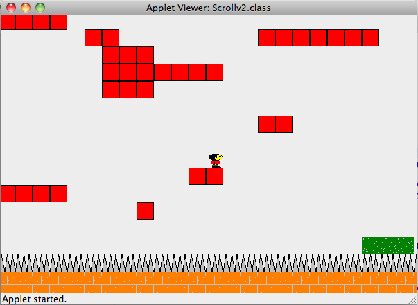
Here is a screenshot of the code in action:


In order to circumvent Java's (admittedly necessary) security measures, all the files are loaded as URLs from the server where they reside. As a result, loading the level takes a really long time. However I couldn't convince Java to read files from a browser so until I find a better way, I'm stuck doing it this way.

The code can be found zipped here or directly here.

You can play the game here (all you need is a little patience.)